Tips for setting up your irrigation system
Back to production guide main page
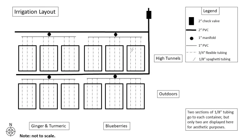
Our site at the Carlsbad Flower Fields was provided access to a water line with a 3 in main threaded ball valve. A 3 in threaded by slip coupling was attached to the main valve and then 3 in PVC and a 3 in elbow were attached. A 3 in to 2 in bushing was installed to reduce the diameter down to 2 in. and then some 2 in PVC was added. A 2 in check valve was then installed and then 2 in PVC was installed across the width of the first three high tunnels, down the length of the first high tunnel, and then across the width of the entire site in between the high tunnels and the outdoor area.
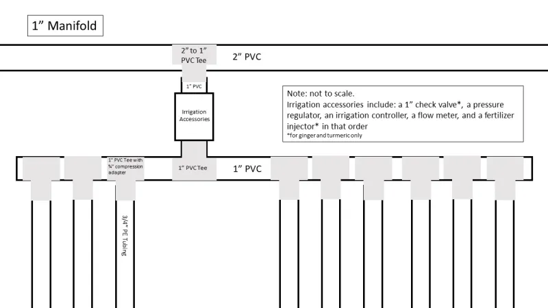
Two inch ball valves were installed to make it easy to flush the lines. Two inch by 1 in slip tee joints were installed in the 2 in lines to feed the 1 in manifolds. The check valve (ginger and turmeric only), flow meter, fertilizer injector (0484A, Mazzei) (ginger and turmeric only), and irrigation controller were installed perpendicular to the 2 in PVC line.
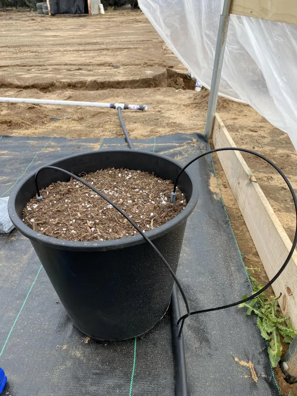
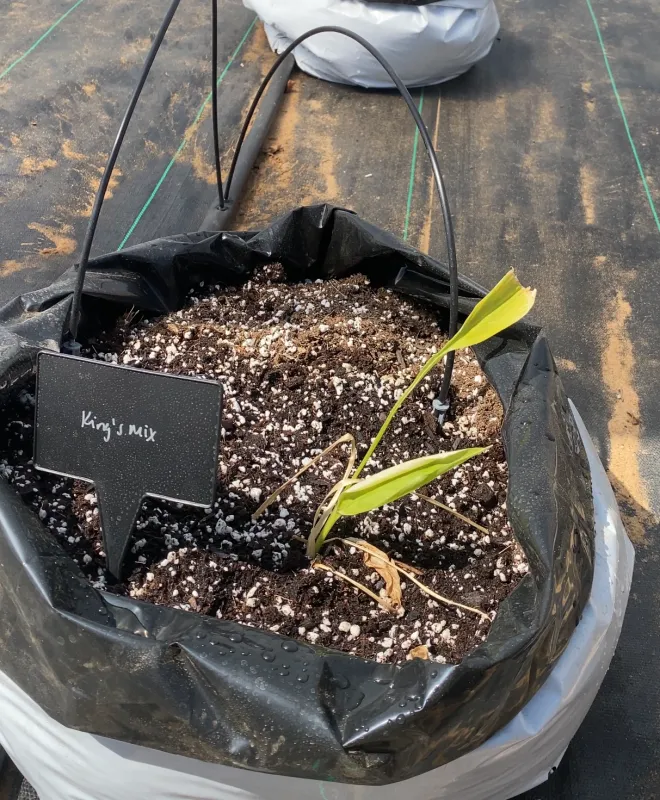
Then a 1 in slip tee joint was used to connect a piece of 1 in PVC with six 1 in slip tee joints with ¾ in compression adaptors to connect the flexible ¾ in tubing going down each row of plants. Flexible 1/8 in tubing (12531-1000, Primerus) was then connected to the ¾ in tubing with a coupler and a grey spot spitter with a 90° spray pattern (SS-AG90GRY-100, Primerus Products LLC) was attached on the other end. Two spot spitters were placed in each container on either side of the plant to thoroughly wet the enter substrate in the pot (Figure 3) or grow bag (Figure 4). See Figure 1 and Figure 2 for a schematic of the irrigation layout and manifold, respectively.


